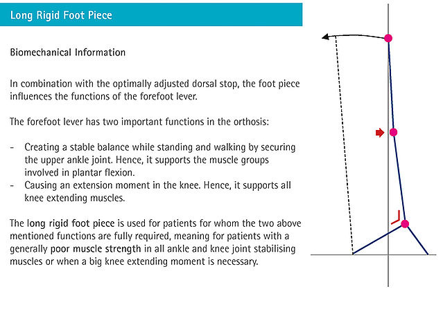
Rigid Foot Piece
The rigid (stiff) foot piece runs from the heel to the tiptoes. Depending on the patient's requirements for the orthosis, a rigid foot piece might be necessary. The biomechanical basics are of help when it comes to choosing the right foot piece.
If you use the Orthosis Configurator, you will receive a recommendation for the foot piece based on the introduced patient data.
Click here to go to the online tutorial for producing a partially flexible foot piece.
-
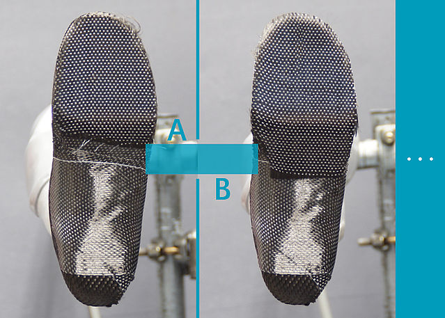
Biomechanical Basics
-
Fase 1/1
-
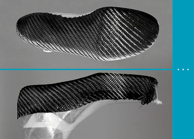
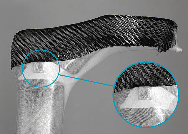
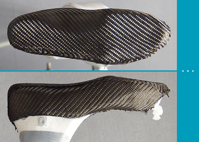
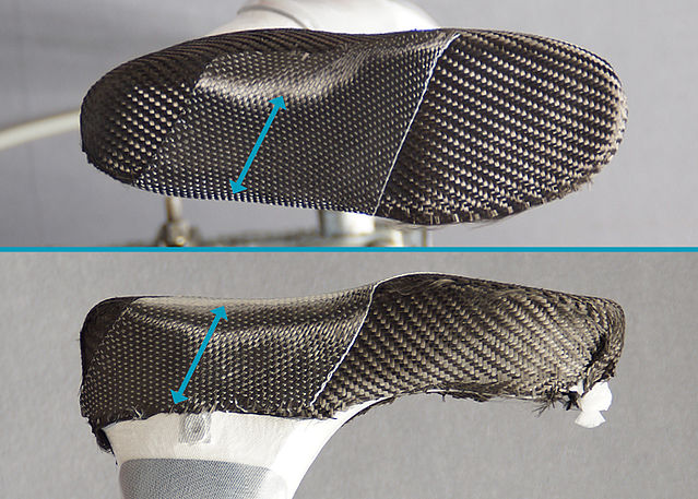
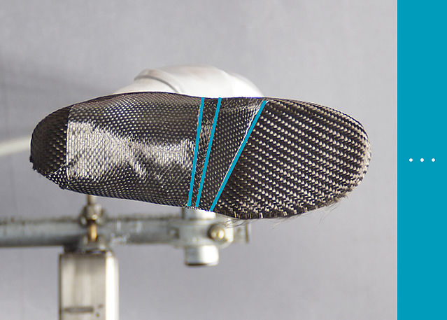
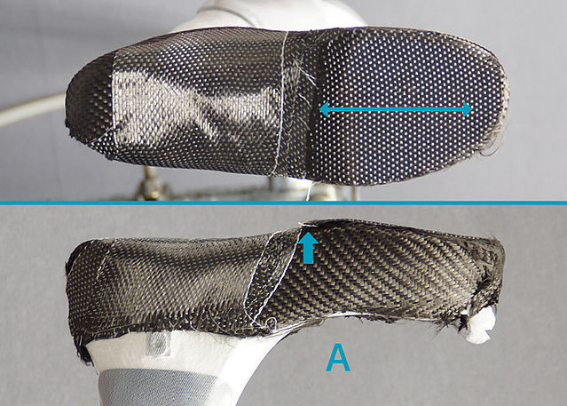
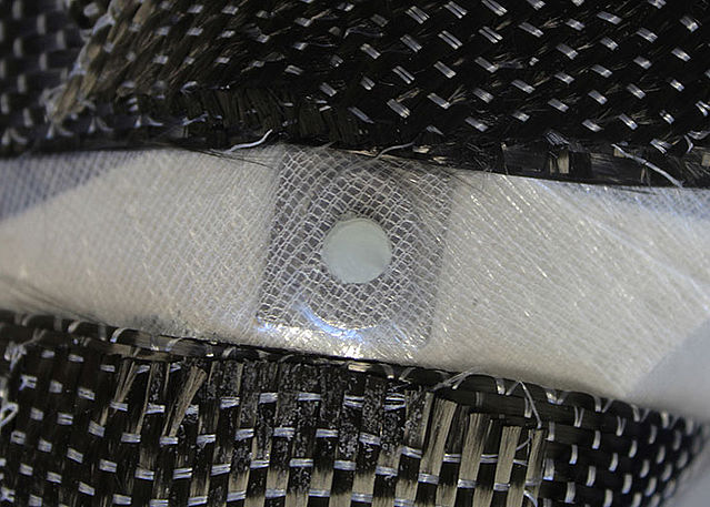
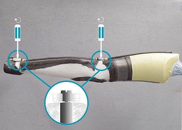
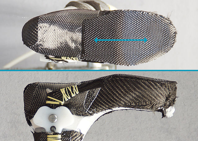
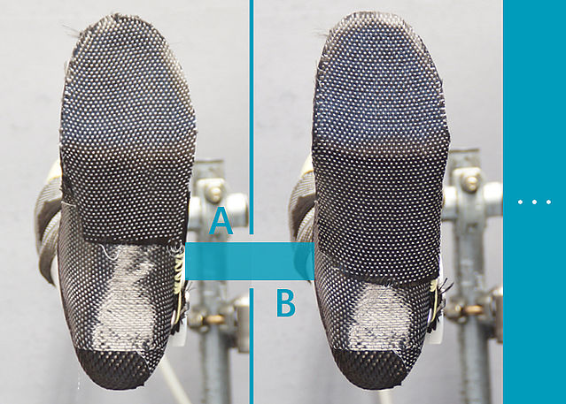
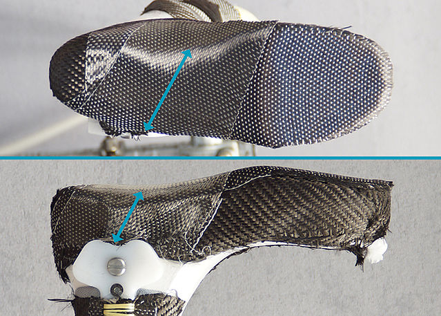
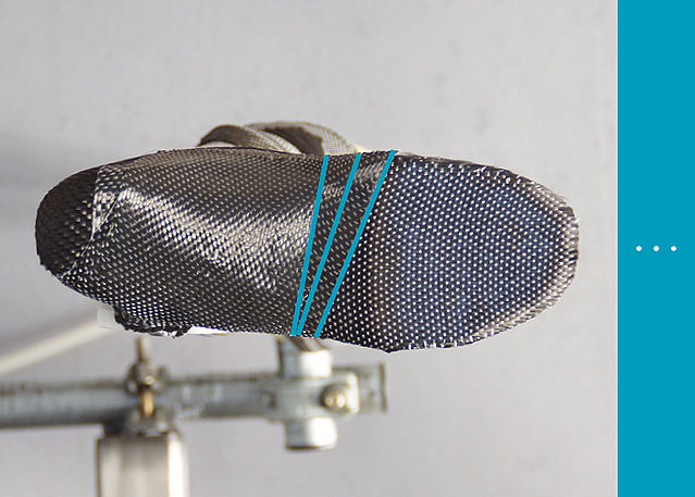
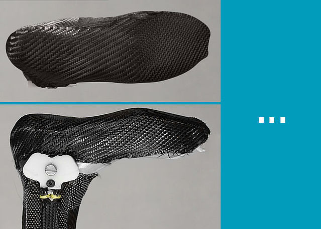
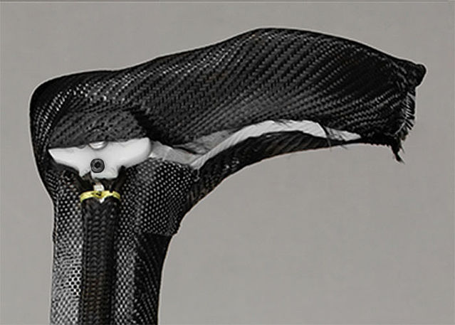
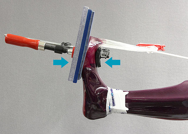
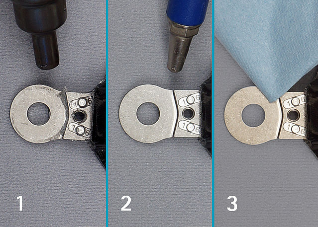
Reinforcing the Foot Piece
-
Fase 1/20

Fase 2/20
Fase 3/20
Fase 4/20
Fase 5/20
Fase 6/20
Fase 7/20
Fase 8/20
Fase 9/20
Fase 10/20
Fase 11/20
Fase 12/20

Fase 13/20
Fase 14/20
Fase 15/20
Fase 16/20
Fase 17/20
Fase 18/20
Fase 19/20
Fase 20/20


-
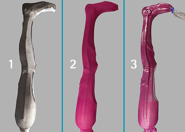
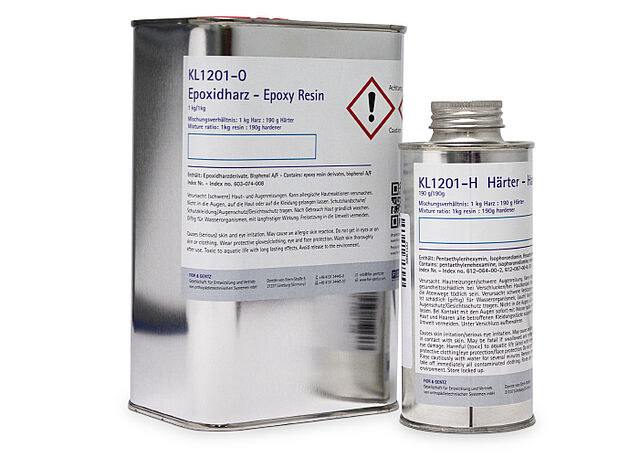
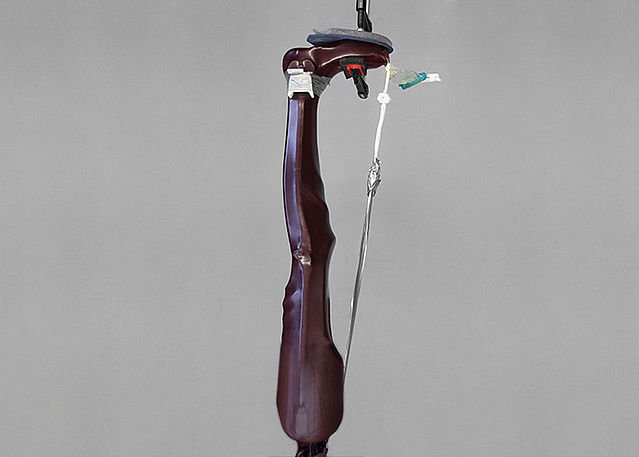
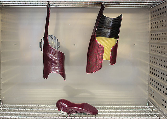
Laminating the Foot Piece
-
Fase 1/3
Fase 2/3
Fase 3/3


-
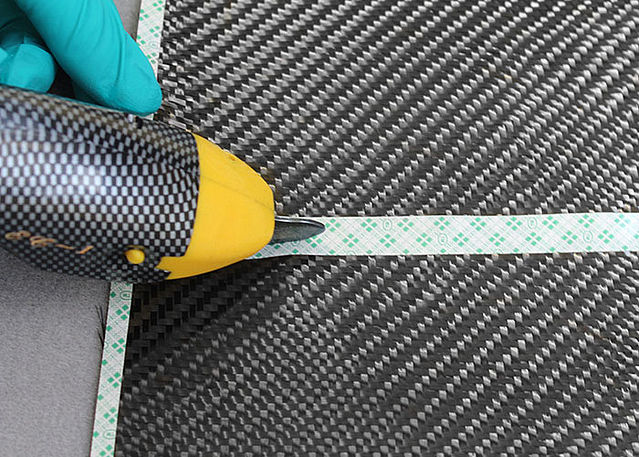
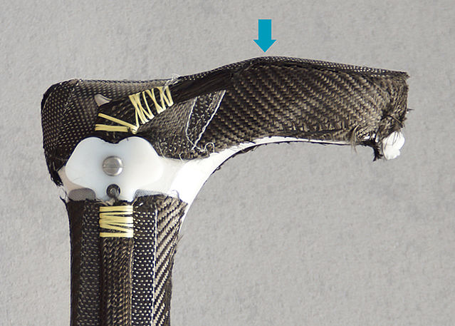
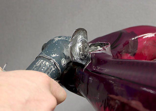
Cutting the Foot Piece
-
Fase 1/2
Fase 2/2


-
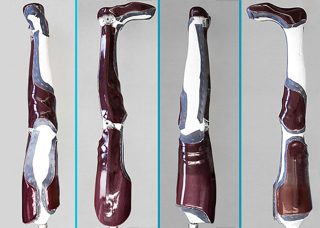
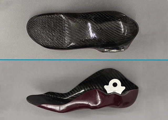
Tempering and Grinding the Foot Piece
-
Fase 1/3
Fase 2/3
Fase 3/3


Last Update: 07 May 2020