KAFO with Carbon System Joints in Anchor Lamination Technique
KAFO with Carbon System Joints in Anchor Lamination Technique
Using NEURO SWING Carbon and NEURO LOCK Carbon as an Example
This online tutorial describes the production of a KAFO with carbon system joints using the NEURO SWING H2O and the NEURO LOCK H2O as an example.
The NEURO SWING H2O system ankle joint as well as the NEURO LOCK H2O system knee joint are equipped with a carbon fibre reinforced joint case and a seawater-resistant stainless steel screwing. Due to its specific sleeves, the spring units of the NEURO SWING H2O are as water-resistant as the carbon fibre reinforced locking parts of the NEURO LOCK H2O.
Due to the properties of the carbon system joints, the production technique for a KAFO (knee-ankle-foot orthosis) differs from the joint lamination technique or anchor lamination technique with system joints made of steel or titanium. The system anchors are specifically designed for the carbon system joints.
You can find the joint assembly of the carbon system ankle joints using the NEURO SWING H2O as an example and the joint assembly of the carbon system knee joints using the NEURO LOCK H2O as an example in the section Options and Extras.
-
Mounting the Assembly/Lamination Dummys
-
Fase 1/1
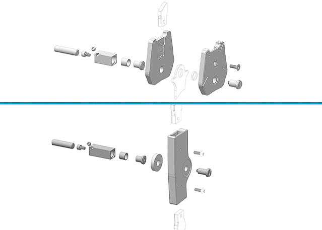
Mount the system joints by using the assembly/lamination dummys and in accordance with the exploded view drawings. When laminating, the dummys serve as placeholder for the system joints’ joint cases.
Note: You can find exploded view drawings in our product catalogue System Joints and Articulated System Side Bars.
-
Bending the System Stirrups/Anchors
-
Fase 1/10
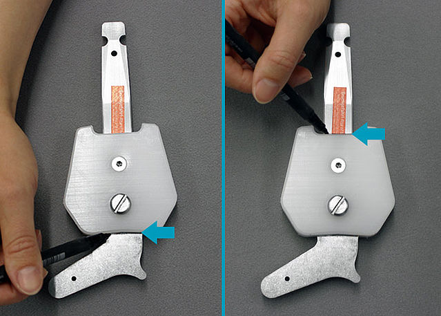
Mark the lower edge of the dummy on the system stirrup and the upper edge on the system anchor. Everything above or below this line must not be bent, as these areas are part of the system joint later.
Note: All waterproof system anchors are also available in a bent shape, which can be used in case of large gaps between system anchor and leg to avoid falling below the bending radii.Fase 2/10
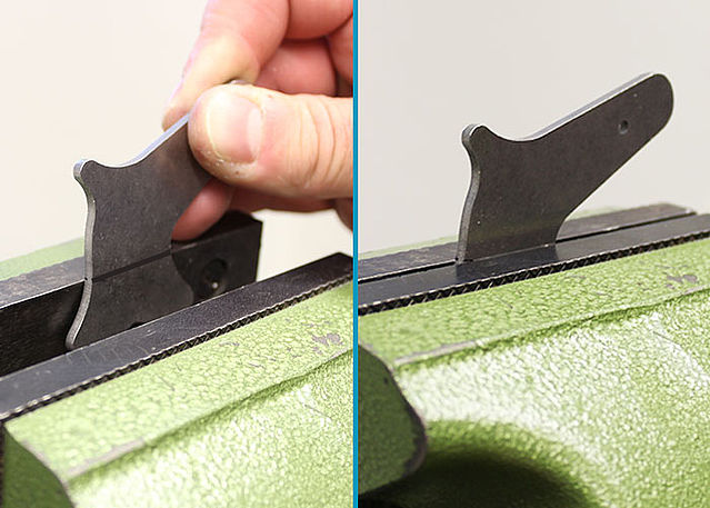
Clamp the system stirrup into a vice with plain jaws to bend it. Pay attention to the marking to avoid a subsequent deformation of the joint areas and to be able to bend very close to the joint.
Fase 3/10
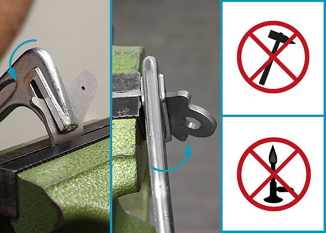
Adapt the system stirrup to the shape of the model. Bend the system stirrup neck with a bending iron. Only bend in one direction.
Note: Do not use a hammer and do not heat the material.Fase 4/10
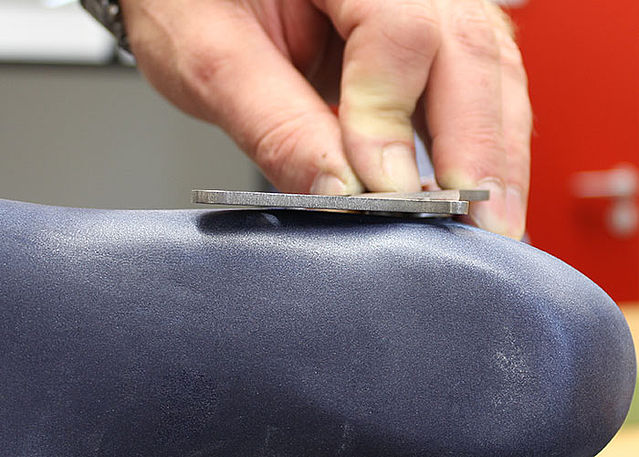
Remove the system stirrup from the vice and check the distance from the system stirrup to the model.
Fase 5/10
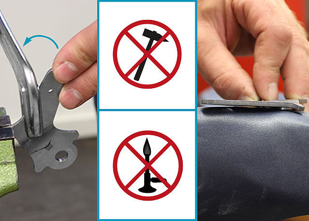
Adapt the system stirrup to the shape of the model. Bend the lower part of the system stirrup with a bending iron. Only bend in one direction.
Check the distance to the model.Fase 6/10
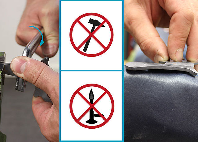
Adapt the system stirrup to the shape of the model. Bend the system stirrup foot with a bending iron. Only bend in one direction.
Check the distance to the model.Fase 7/10
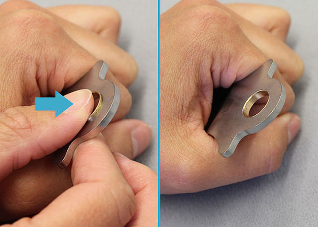
In case the sliding bushing fell out during the bending process, grease it slightly and place it into the bore at the system stirrup again.
Fase 8/10
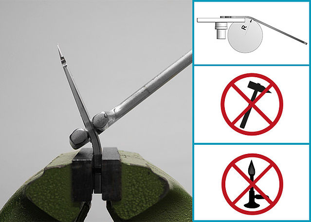
Clamp the system anchor into a vice with plain jaws to bend it. Pay attention to the marking to avoid a subsequent deformation of this area which is adhered to the joint later. While bending, please consider the applicable bending radii and use proper tools (bending iron with round edges).
Note: You will find more detailed information in the Instructions for Use for Orthotists or Qualified/Trained Experts for System Anchors for Waterproof System Joints.Fase 9/10
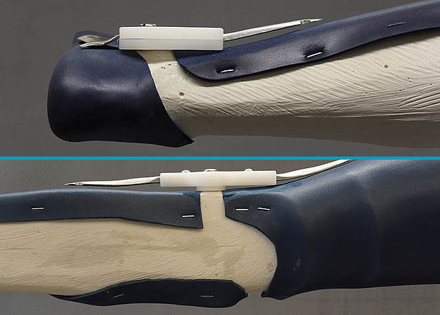
Check the distance from system anchors and stirrups to the positive cast. Please make sure to have enough space left for the reinforcing profile and the reinforcement layers in order to avoid later strains to the laminate. Thus, the joint areas stay parallel.
Fase 10/10
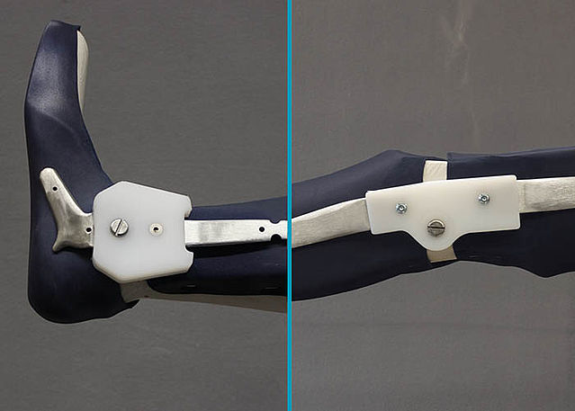
Grind the system stirrup and the system anchor. Always grind in direction of rolling. Remove all notches from bending and avoid sharp edges.
Note: System ankle joints with dorsiflexion stop, which can be adjusted by filing, should always be mounted in their pre-assembled neutral position without changing the dorsiflexion stop.


-
Reinforcing and Laminating the KAFO
-
Fase 1/1
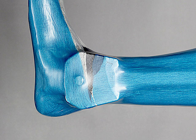
Use a profile core and produce the system string. Reinforce as usual. You do not need a shaping dummy.
Important! Please note the processing instructions and the safety data sheet for our epoxy resin and hardener.
-
Cutting the KAFO
-
Fase 1/4
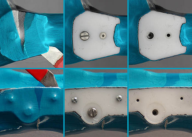
Use a sharp knife to remove the thin laminate layer over the dummies. Remove the screws.
Fase 2/4
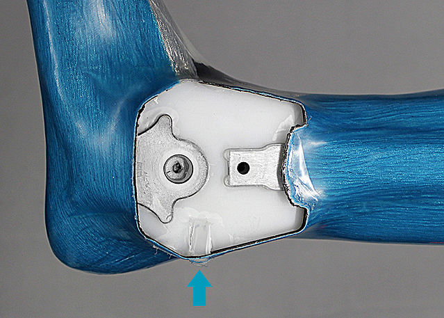
Carefully lever the dummy of the system ankle joint out of the laminate at the marked spot (arrow). Make sure not to damage the joint areas of the system stirrup in the process. The dummy of the system knee joint cannot be removed, it remains in the laminate.
Fase 3/4
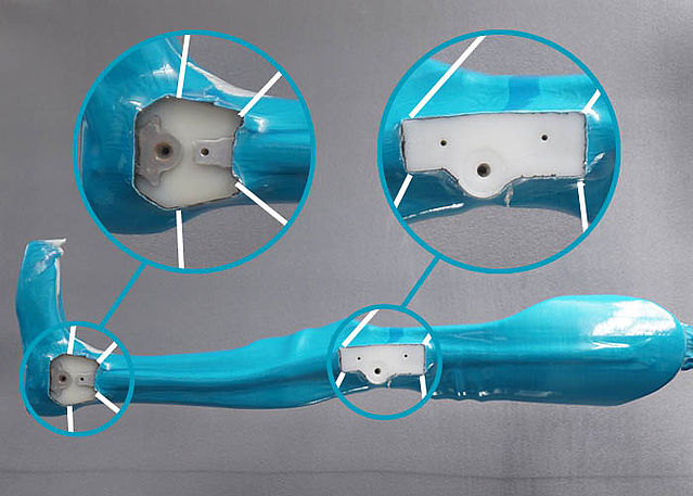
Mark the cutting edges by following the previously modified edge of the later orthosis. For optimally integrating the system joint and gaining the maximum possible bearing surface at the foot piece, only remove as much of the laminate as necessary and as little as possible.
Fase 4/4
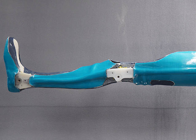
Remove all laminate parts which are no longer necessary. Then, you can remove the orthosis parts from the model.


-
Tempering and Grinding the KAFO
-
Fase 1/4
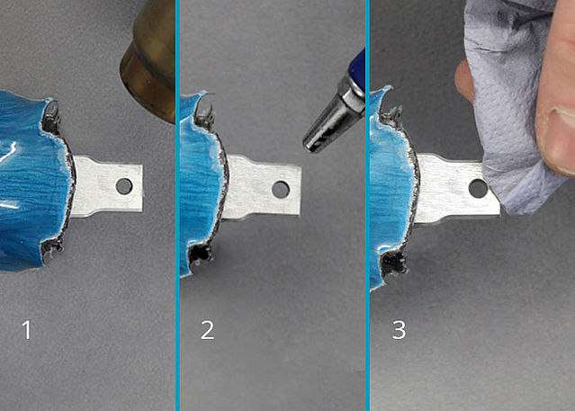
Clean all the joint areas as well as the system stirrup before you temper the parts of the orthosis. Heat all wax residues with a hot air blower (1) and blow
the liquefied insulating wax out of the hollows (2). Remove all residues with a cloth (3). Remove the PVA film tube as well.Fase 2/4
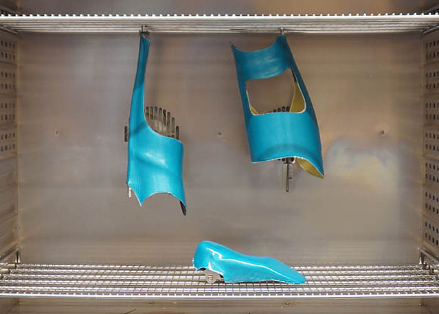
Temper all parts of the orthosis before you grind them. Place the orthosis parts into a cold convection oven and heat it up slowly. When tempered, the parts of the orthosis are stable and can be worked in the best possible way.
Important! Also follow the processing instructions for epoxy resin.Fase 3/4
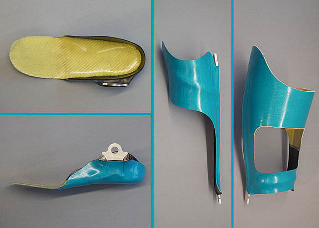
Grind the edges of the orthosis parts (e.g. with an belt grinder). However, it is essential to avoid predetermined breaking points in the metal! Also make sure that the flexible area of the foot piece is even (without brinks).
Note: Apply some insulating wax to the aramid fibre edges and subsequently grind them with coarse sandpaper.Fase 4/4
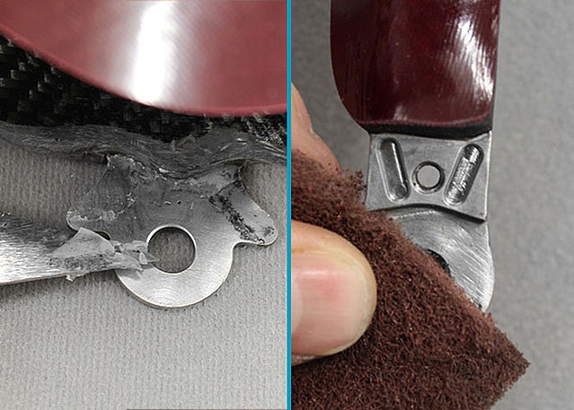
In order to remove all possibly caused notches, remove remaining resin residues from the system stirrup with a sharp knife and polish the stirrup subsequently (e.g. with a marbling tool). Clean all screw drives (e.g. with LOCTITE® 7063 Super Clean) in order for the screws to be effectively fixed later on.
Note: Mind the safety data sheet when using the Super Clean LOCTITE® 7063.


-
Mounting the System Joints
-
Fase 1/1
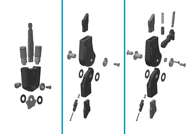
Mount the system joints as described in the respective online tutorials on the joint assembly of the carbon system joints.
In the picture, you can see the individual parts of the NEURO SWING H2O system ankle joint as well as the system knee joints NEURO CLASSIC H2O and NEURO LOCK H2O.
Last Update: 27 October 2020