Locked System Knee Joints
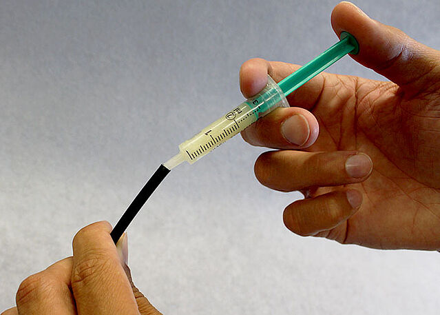
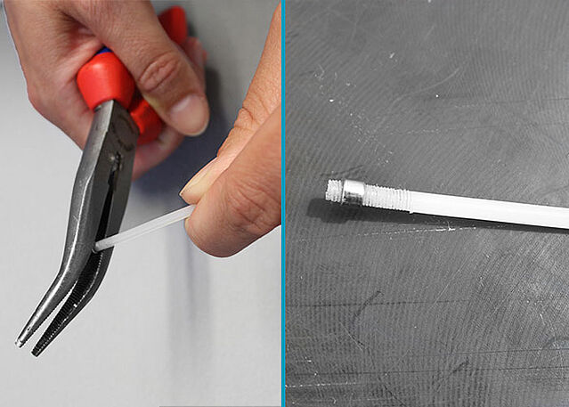
Preparing and Mounting the Pulling Cable
Orthoses with a locked system knee joint are often equipped with a pulling cable for the patient to be able to unlock the orthosis in an easy and comfortable way. The following tutorial shows how a KAFO with a unilateral pulling cable.
If you produce a bilateral orthosis, you can proceed the same way. But, you skip the loop and direct the pulling cable from one pulling cable adaptor to the other instead.
You will find further information on the pulling cable in the respective instructions for use.
-
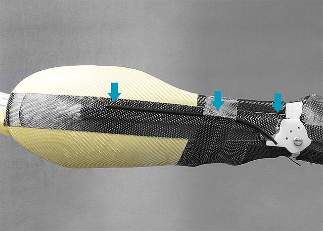
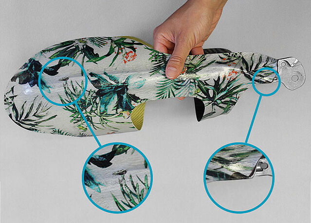
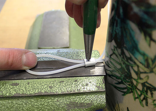
Positioning the Pulling Cable Conduit
-
Fase 1/6
Fase 2/6
Fase 3/6
Fase 4/6
Fase 5/6

Fase 6/6


-
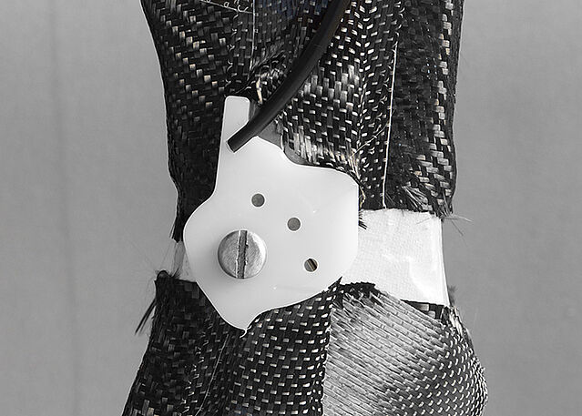
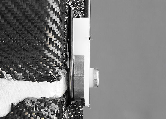
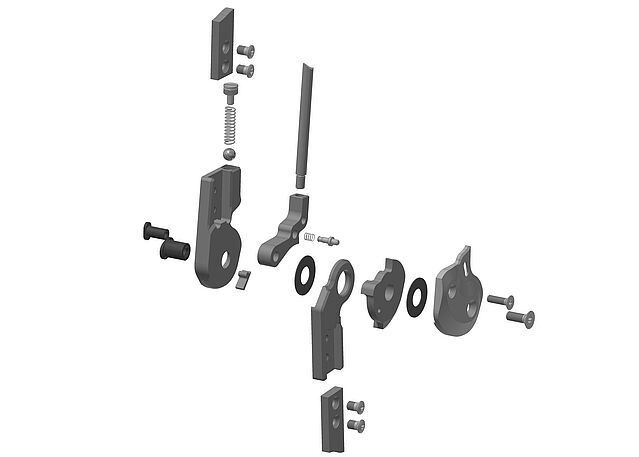
Mounting the System Joints
-
Fase 1/1
-
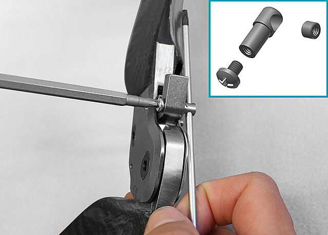
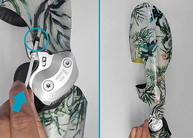
Mounting the Pulling Cable
-
Fase 1/6
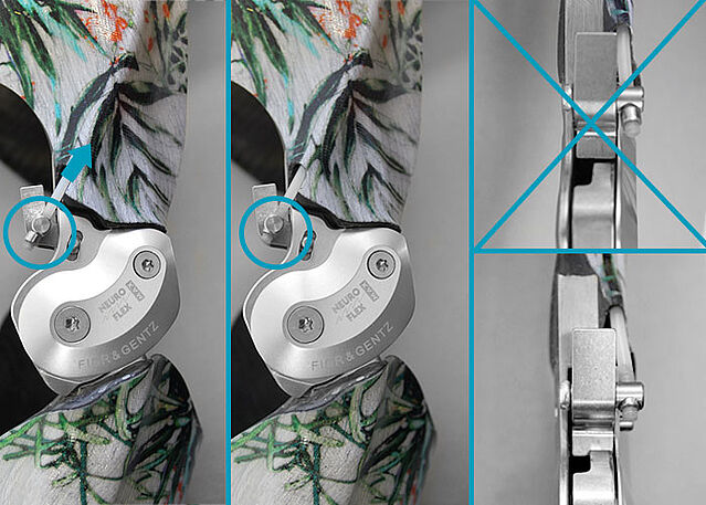
Fase 2/6
Fase 3/6
Fase 4/6
Fase 5/6
Fase 6/6


Last Update: 25 August 2020